 Türkçe
Cable Trays | Industrial Cable Management Systems
Industrial Cable Tray Systems for Safe and Organized Power Routes
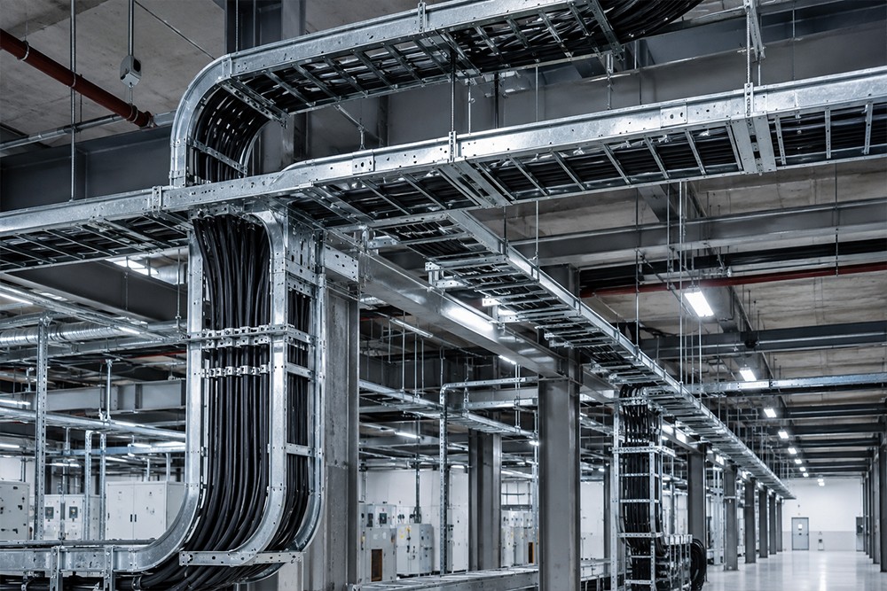
Cable tray systems are metal infrastructure systems used to carry power, control, automation, data and low-voltage cables safely, systematically and accessibly in factories and industrial facilities. They protect cables from mechanical effects, simplify maintenance access and support controlled management of electrical infrastructure.
Each system is engineered specifically according to cable type, total weight, fill ratio, route, support spacing, environmental conditions, fire penetrations and future capacity requirements.
What Is a Cable Tray?
A cable tray is a modular metal carrying system that supports and protects electrical and automation cables along horizontal or vertical routes.
Depending on project requirements, the system may include:
- Perforated cable trays
- Cable ladder systems
- Wire-mesh cable trays
- Covered cable trunking
- Vertical riser and drop components
- Bends, tee pieces and reducers
- Suspension rods and brackets
- Supporting profiles
- Dividers and covers
- Earthing and connection accessories
Advantages of Cable Trays
Carry Cables Safely
Keep power, control and communication cables on fixed routes and reduce crushing, cutting and sagging risks.
Improve Route Organization
Allow cable groups to be separated according to function and voltage level.
Simplify Maintenance and Fault Intervention
Accessible routes make inspection, additional cable installation and fault detection faster.
Support Heat Dissipation
Perforated and ladder-type systems allow airflow and help limit heat accumulation.
Allow Future Expansion
Tray systems designed with spare capacity can be extended when the facility grows.
Support Occupational Safety
Help prevent cables from being left loosely on floors, machinery and access routes.
Types of Cable Trays
Perforated Cable Trays
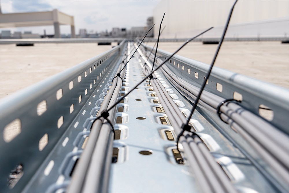
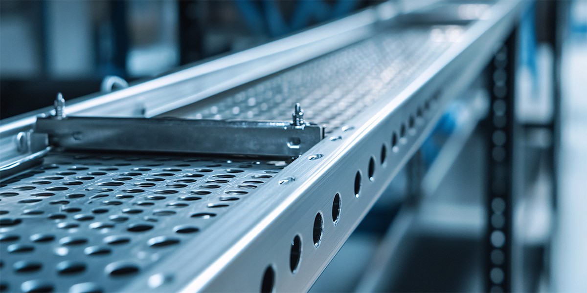
Versatile systems used for light- and medium-density power, control and data cables.
Cable Ladder Systems
Preferred for heavy power cables, long spans and applications requiring high airflow.
Wire-Mesh Cable Trays
Provide fast installation and easy direction changes for data, automation and light cable routes.
Covered Cable Trunking
Protect cables in areas exposed to dust, liquid splash or mechanical impact.
Vertical Cable Trays
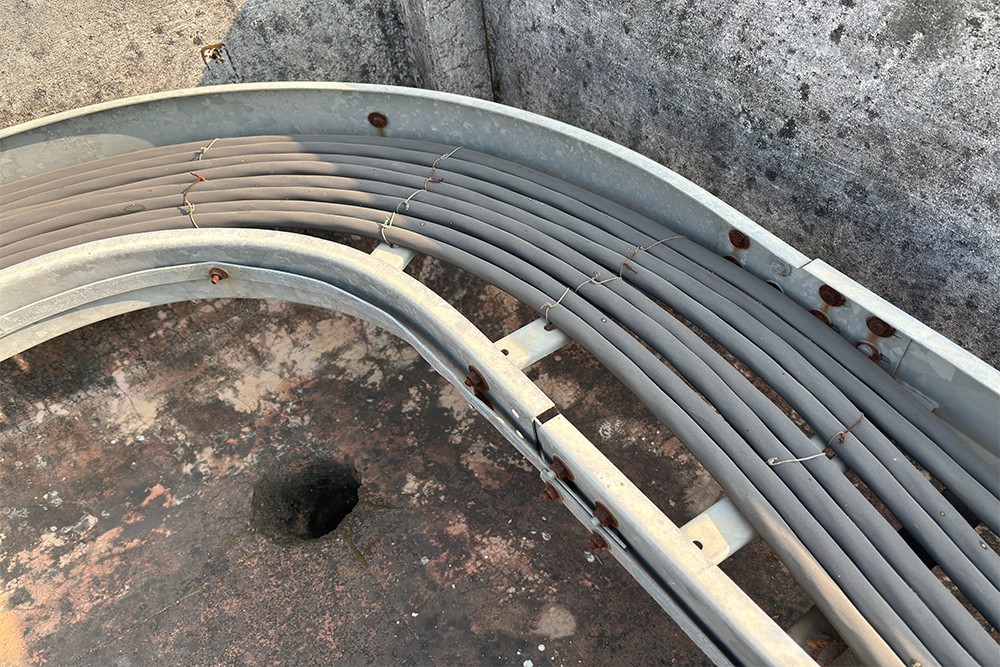
Secure cables on vertical routes between floors, platforms and machinery levels.
Heavy-Duty and Custom-Designed Trays
Reinforced for dense cable loads, large conductors, long spans and non-standard routes.
Key Design Considerations
- Cable types, cross-sections and total weight
- Current and future fill ratio
- Tray width, height and sheet thickness
- Support and suspension spacing
- Horizontal and vertical routes
- Bends, tee pieces and reduction points
- Separation of power, data and low-voltage lines
- Temperature, humidity and chemical exposure
- Maintenance and intervention access
- Fire compartments and penetrations
- Earthing and electrical continuity
- Mounting surface and anchoring conditions
Application Areas
- Manufacturing facilities
- Automotive and supplier industries
- Metalworking factories
- Food and beverage plants
- Chemical and pharmaceutical facilities
- Energy and transformer facilities
- Warehouses and logistics centers
- Robotics and automation lines
- Data and communication infrastructure
- New facilities and capacity-expansion projects
Our Production and Installation Process
Each project is evaluated individually according to cable load, route and site conditions.
1. Requirements Analysis and Site Survey
Cable types, cross-sections, total weight, start-end points, mounting surfaces and existing infrastructure are evaluated.
2. Route and System Design
Tray type, dimensions, support spacing, bends, rises and drops, brackets, anchors and spare capacity are determined.
3. Manufacturing
Sheet metal, profiles, brackets, hangers and custom connection components are cut, drilled, bent and assembled according to project dimensions.
4. Surface Treatment and Quality Inspection
Powder coating, pre-galvanized sheet, hot-dip galvanizing or stainless steel is selected. Dimensions, connections and surface quality are inspected.
5. Site Installation
Hangers, brackets, trays, route fittings and covers are installed; alignment and connections are completed.
6. Final Inspection and Handover
Route continuity, support spacing, connections, maintenance access and site compatibility are checked before handover.
Modification and Expansion of Existing Cable Tray Systems
New machinery, capacity increases or higher cable density may make existing systems insufficient. Deformation, corrosion, loose hangers, route sagging and uncontrolled cable additions can also reduce safety.
Following a technical inspection, the following works may be carried out:
- Tray and cover replacement
- Hanger and bracket reinforcement
- Addition of new routes
- Vertical-route modification
- Addition of trays and connection components
- Installation of cable dividers
- Renewal of earthing connections
- Capacity increase
- Surface-coating renewal
Material and Surface Options
Material and coating are selected according to corrosion level, hygiene requirements, outdoor exposure and chemical conditions.
Pre-Galvanized Sheet Steel
Provides an economical and corrosion-resistant solution for indoor and semi-open industrial areas.
Hot-Dip Galvanized Steel
Provides long-term protection in outdoor, humid and highly corrosive environments.
Stainless Steel
Provides hygiene and high corrosion resistance for food, chemical, pharmaceutical and wash-down areas.
Electrostatic Powder Coating
Can be used for indoor applications requiring corporate colors or visual separation.
Steel Supporting Profiles
Used for brackets, hangers, stands and main support structures with sections selected according to load calculations.
Connections and Accessories
Fittings, dividers, covers, threaded rods, brackets, bolts and earthing components can be included.
Why Nevas Çelik?
Projects are not limited to standard cable-tray dimensions; they are prepared according to actual cable load, route, supporting structure, environmental conditions and future capacity requirements.
Site survey, technical design, steel fabrication, surface treatment and site installation are managed within a single process. Repair, reinforcement, route addition and capacity increase can also be carried out on existing systems.
Information Required for a Quotation
- Cable types and approximate total quantity
- Cable cross-sections or total weight
- Preferred tray type
- Required tray width and height
- Start and end points
- Approximate route length
- Bends, rises, drops and penetration points
- Ceiling, wall or structural mounting preference
- Environmental and corrosion conditions
- Preferred material and surface treatment
- Installation and delivery location
Frequently Asked Questions
What is a cable tray used for?
It carries power, control, data and automation cables along safe, organized and accessible routes.
Are cable trays manufactured in standard dimensions?
Standard sizes may be available, but routes, bends, hangers, brackets and custom parts are prepared according to the project.
Which tray is suitable for heavy power cables?
Cable ladders or reinforced heavy-duty trays are generally preferred for heavy and large-section cables.
Can cable trays be used outdoors?
Yes. Hot-dip galvanized steel, stainless steel or project-specific protective coatings can be used.
Can an existing cable-tray route be expanded?
Yes. New routes, trays, brackets and connection parts can be added after a suitability assessment.
Do cable trays require earthing?
Electrical continuity and earthing requirements for metal systems should be evaluated according to the electrical design and applicable standards.
A Project-Specific Solution for Safe and Organized Power Routes
Technical assessment and project engineering can be provided for a cable tray system suited to your cable density, route and facility conditions.
You can request a quotation for a new installation, modification of an existing route or capacity increase by sharing your project information.