 Türkçe
Jigs and Fixtures | Industrial Manufacturing Solutions
Industrial Jigs and Fixtures for Accurate, Fast and Repeatable Production
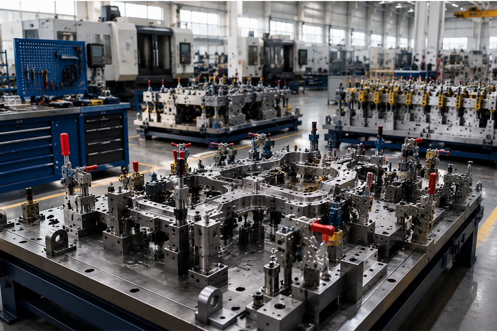
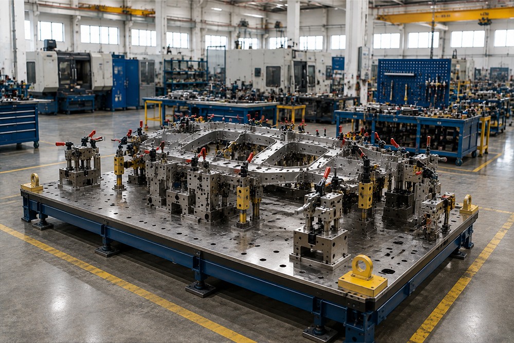
Jigs and fixtures are production auxiliary systems used to position, guide and secure parts during manufacturing, welding, assembly, inspection and measurement operations. They reduce operator dependency, standardize repetitive processes and help maintain dimensional consistency in serial production.
Each system is engineered specifically according to part geometry, tolerances, production volume, process type, datum surfaces, clamping points, cycle-time targets, ergonomics and automation requirements.
What Are Jigs and Fixtures?
A jig positions the workpiece and also guides a drill, cutter or similar tool during the operation.
A fixture positions and secures the workpiece against defined datums and holds it stable throughout the process. It does not directly guide the tool; its primary purpose is to ensure part location and repeatability.
Depending on project requirements, the system may include:
- Steel-profile or plate supporting frame
- Locating pins and stops
- Mechanical, pneumatic or hydraulic clamps
- Quick-action clamps
- Bushings and tool-guidance elements
- Adjustable supports and pressure pads
- Rotary or tilting mechanisms
- Part-presence and position sensors
- Inspection and measurement points
- Modular and removable connections
Advantages of Jigs and Fixtures
Provide Dimensional Repeatability
Ensure that the part locates against the same datums in every cycle and help limit production variation.
Reduce Cycle Time
Quick clamping, controlled loading and easy part removal help improve production speed.
Reduce Operator Dependency
Defined loading direction, position and clamping sequence reduce differences between operators.
Help Prevent Incorrect Loading
Poka-yoke details, locating pins, stops and sensors limit incorrect orientation or incomplete placement.
Support Welding and Assembly Quality
Hold parts stable throughout the process and help reduce gaps, misalignment and deformation.
Offer a Modular and Upgradeable Structure
Replaceable modules allow the system to be updated for product revisions, new variants or capacity increases.
Types of Jigs and Fixtures
Welding Fixtures
Hold sheet-metal and profile components in the correct geometric position and help limit misalignment and deformation during welding.
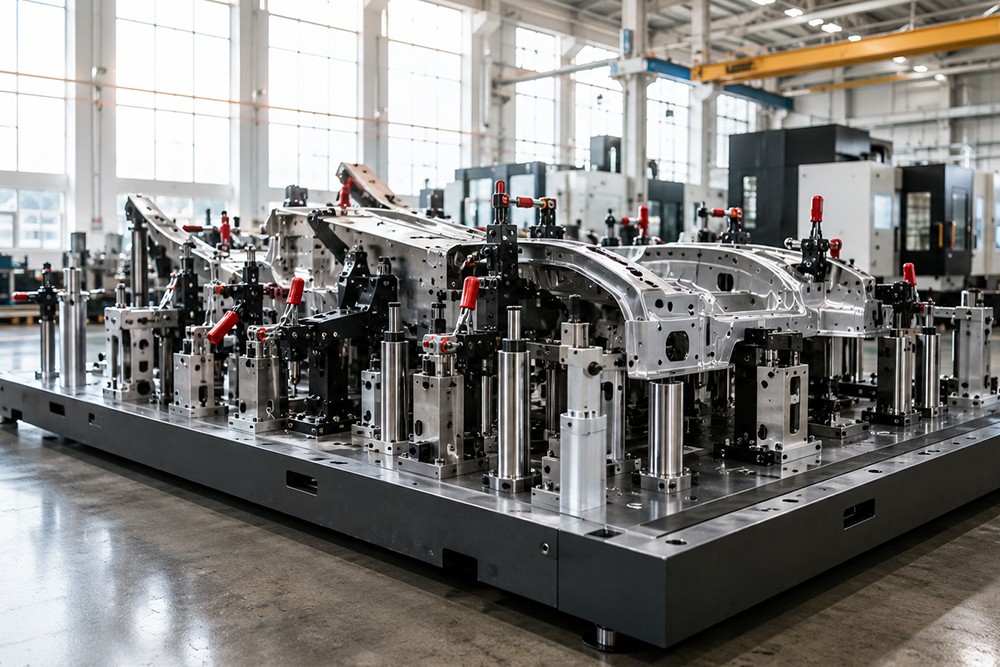
Assembly Fixtures
Support the joining of multiple components according to defined sequence and datums.
Drilling Jigs
Use guide bushings and tool-guidance elements to direct drilling or cutting tools accurately.
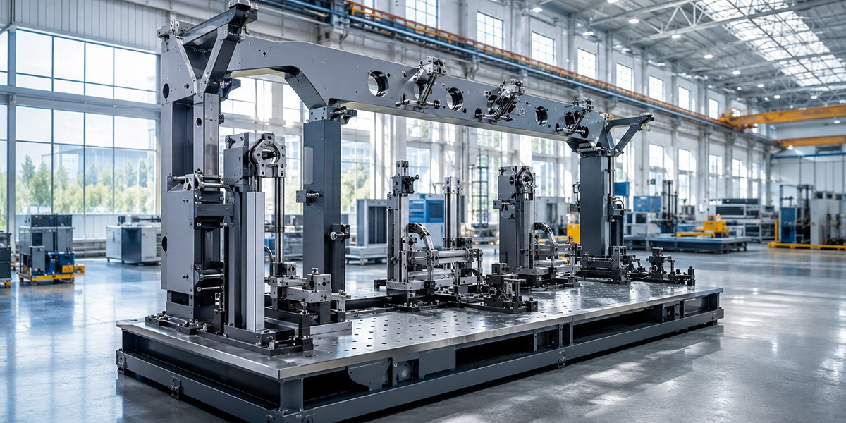
Inspection Fixtures
Provide fast checking of dimensions, form, hole position and datum points on manufactured parts.
Robotic Welding and Automation Fixtures
Prepared according to robot access, sensors, pneumatic clamping and automated cycle scenarios.
Rotary and Tilting Fixtures
Use manual, pneumatic or motorized mechanisms to provide access to different surfaces of the part.
Key Design Considerations
- Part dimensions and geometry
- Technical tolerances
- Primary and secondary datum surfaces
- Part loading and unloading direction
- Clamping points and forces
- Welding or process sequence
- Thermal distortion and part movement
- Tool, robot and operator access
- Cycle-time target
- Sensor and poka-yoke requirements
- Ergonomics and occupational safety
- Future product variants
Application Areas
- Automotive and supplier industries
- Welded fabrication
- Metal forming
- Machinery and equipment manufacturing
- White-goods production
- Defense and aerospace
- Plastic and rubber component assembly
- Electronic and electromechanical assembly
- Quality-control and inspection areas
- Robotics and automation lines
Our Production Process
Each project is evaluated individually according to part geometry, process requirements and production scenario.
1. Requirements and Technical Data Analysis
Part drawings, 3D models, tolerances, process sequence, production volume, cycle time and quality criteria are evaluated.
2. Datum and System Design
Locating points, pins, supports, clamping points, tool access, sensors and operator movements are determined.
3. Technical Engineering and Manufacturing
The supporting frame, machined plates, pins, bushings, stops and custom parts are produced according to technical drawings.
4. Assembly and Surface Treatment
Components are assembled accurately, and grinding, coating, paint, black oxide or corrosion protection is applied where required.
5. Dimensional, Functional and Repeatability Inspection
Datum points, clamping movements, sensors, part loading and dimensional stability over repeated cycles are checked.
6. Trial Production and Handover
Trial runs are completed with actual or sample parts, final adjustments are made and the system is handed over with operating and maintenance information.
Modification and Development of Existing Jigs and Fixtures
Product changes, new variants, capacity increases, wear, clamping problems or dimensional variation may require existing jigs and fixtures to be modified.
Following a technical inspection, the following works may be carried out:
- Renewal of locating pins and stops
- Replacement of worn bushings
- Modification of clamping elements
- Conversion to pneumatic or hydraulic clamping
- Addition of sensors and poka-yoke
- Addition of modules for new product variants
- Reinforcement of frames and supporting plates
- Improvement of robot and operator access
- Dimensional adjustment and calibration
Material, Surface and Equipment Options
Materials and equipment are selected according to process type, accuracy requirements, cycle quantity and operating environment.
Carbon-Steel Profiles and Plates
Provide durable and cost-effective solutions for supporting frames and primary structures.
Machined Tool Steels
Used for locating pins, bushings, stops and precision components exposed to wear.
Aluminum Plates and Profiles
Can be considered where low weight, easy machining and fast modification are required.
Stainless Steel
Can be used in special projects requiring hygiene, humidity resistance or high corrosion protection.
Pneumatic and Hydraulic Clamping Components
Preferred where high cycle speed and controlled clamping force are required.
Sensors and Control Equipment
Part-presence sensors, position sensors, switches and error-proofing components can be integrated.
Why Nevas Çelik?
Projects are not limited to standard fixture structures; they are prepared according to actual part geometry, tolerances, process sequence, cycle time and operator or robot access.
Technical design, steel fabrication, precision machining, assembly, inspection and trial processes are managed within a single project. Mechanical, pneumatic, sensor-equipped and modular modifications can also be carried out on existing jigs and fixtures.
Information Required for a Quotation
- 2D technical drawing or 3D model of the part
- Part dimensions and tolerances
- Annual or daily production quantity
- Process type
- Welding, drilling, assembly or inspection sequence
- Manual, pneumatic or hydraulic clamping preference
- Operator or robot-use information
- Cycle-time target
- Critical dimensions to be inspected
- Sensor and poka-yoke requirements
- Machine or production-line information
- Photographs and dimensions for existing-fixture modification
Frequently Asked Questions
What is the difference between a jig and a fixture?
A jig positions the workpiece and guides the tool. A fixture positions and secures the workpiece against defined datums.
Are jigs and fixtures manufactured in standard dimensions?
No. They are designed specifically according to part geometry, tolerances, process and production scenario.
Can pneumatic or hydraulic clamping be applied?
Yes. Pneumatic or hydraulic systems can be used according to cycle-time and clamping-force requirements.
Can fixtures be manufactured for robotic welding lines?
Yes. Robot access, welding sequence, sensors and automation communication can be considered in the design.
Can inspection fixtures be manufactured?
Yes. Custom inspection fixtures can be produced for fast checking of critical dimensions, holes, form and datum points.
Can an existing fixture be adapted to a new product?
Yes. Datum points, clamping locations, modules, sensors and supporting structures can be modified where suitable.
A Project-Specific Solution for Accurate and Repeatable Production
Technical assessment and project engineering can be provided for a jig and fixture system suited to your part geometry, tolerances, cycle time and manufacturing process.
You can request a quotation for a new system, modification of an existing fixture or pneumatic, sensor-equipped and modular upgrades by sharing your project information.